BS type sewage wells are manufactured from:
- watertight [W12]
- small-absorbent [less than 4%]
- frost resistant [F-150]
high quality concrete - class not lower than C35/45
Prefabricated products are produced in diameters:
- 1000 mm
- 1200 mm
- 1500 mm
and as street gullies - in diameter 450 mm
BS type wells are used in sanitary, industrial, rainwater and general sewage systems to connect pipes in the range of DN to 1.0 m, made of all available materials used to build sewage networks.
The basis for the production of BS type wells is PN-EN1917:2004 standard and National Technical Assessment issued by the IBDiM in Warsaw.
BS-type wells may have the following functions:
- through wells
- junction wells
- cascade wells
- blind wells [in rainwater drainage systems]
PRODUCTION TECHNOLOGY AND APPLICATION GUIDELINES
Prefabricated concrete and reinforced concrete elements for the construction of wells are manufactured in accordance with PN-EN1917:2004 ( DN1000, DN1200) and the National Technical Assessment (DN1500), which specify:
- types of elements
- dimensions
- structural reinforcement of reinforced concrete elements
- requirements for static and transport reinforcement
- requirements for raw materials used for
production of prefabricated elements
- the type of connection of the elements
- strength and watertightness requirements
- type of control tests
GENERAL DATA
Elements for street gullies DN=450mm are made of the same concrete as BS type sewage drains.
The basis for the execution is PN-EN 1917:2004 standard and National Technical Assessment issued by the IBDiM in Warsaw (for relief rings).
The wells are designed to drain surface water from roadways, parking lots, squares etc. in rainwater drainage systems.
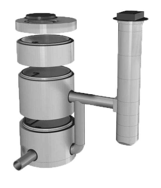
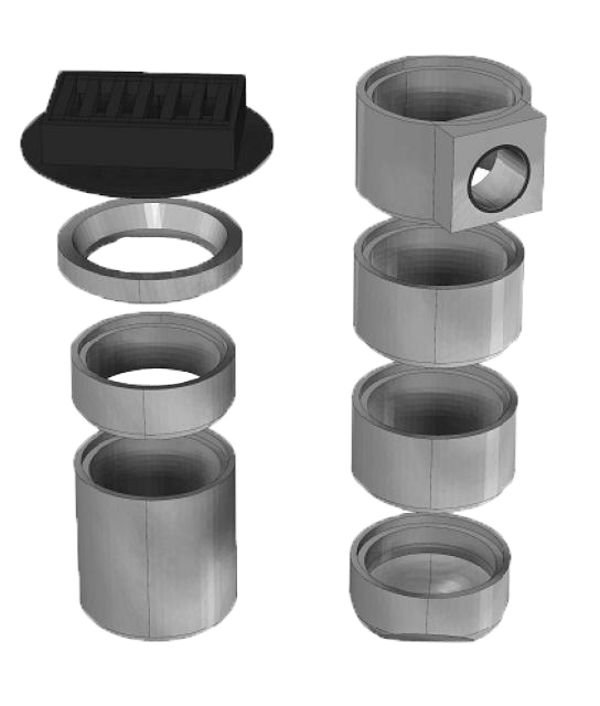
COMPONENTS OF A GULLY
- settling tank bottom
- intermediate disks
- connection piece
- equalisation [reduction] ring
- relief ring
The selection of elements should be made in such a way as to ensure that an appropriate manhole height is achieved, and in the case of settling tanks, at least 0.5 m of settling tank [space between pipe slide and manhole bottom].
The manhole height is adjusted by means of intermediate discs, which are produced in three heights: h=195mm, 295mm, 570mm.
In the connection element there is a tight passage for DN160PCV or DN200PCV pipe installed in the factory.
The top of the manhole is a reduction ring or a relief ring, on which the drain is mounted.
INSTALLATION
Before starting the assembly, all the dirt that has occurred during transport and unloading must be removed from all elements.
The connecting parts must be moistened before assembly.
Use suitable concrete mortar to connect the individual elements.
CONSTRUCTION GUIDELINES
Concrete manholes for street gullies are designed to be built into the sewage system used for drainage of roads, communication routes, drainage of land situated in or outside the roadway strip, near curbs, in parking areas, hardened shoulders. The place of foundation of the gully depends on the class of its finial.
Concrete sewage drains should be installed in a prepared, dehydrated trench, directly on the native soil, sand bedding, concrete base or foundation, depending on water and ground conditions, as specified in the construction design. The gully tops should meet the requirements of PN-EN 124:2000 standard.
The connections between the individual elements of the gully should be grouted and smoothly trowelled with cement mortar. The connection of the concrete sewage sump with the sewage pipe is made by means of a tight passage built into the connection element.